PT Anchorages
PT Anchorages are carefully designed steel anchors that work behind the scenes, channeling powerful forces from prestressing tendons straight into the core of our structures. Whether discreetly concealed or elegantly showcased, these anchors serve as the steadfast support that keeps bridges, stadiums, and buildings resilient and reaching new heights. Next time you gaze at a concrete marvel, take a moment to appreciate the subtle strength of these unsung champions.
- Anchor Cone
- Anchor Head
- Wedges
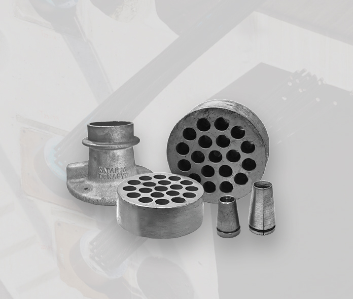
Anchor Cone (Tube Unit)
The Anchor Cone helps transfer the force from the Anchor Head to the concrete segment. It guides the high-tension strand into the duct, ensures a good fit, and allows for easy grout injection. This component is typically made of Cast Iron and is commonly used in prestressed concrete segments and girders.
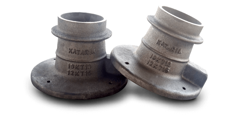
Anchor Cone (Tube Unit)
Technical Specification
| Sr.No. (mm) | HTS Size | Anchor Cone (code) | TD Top ID (mm) | BD Bottom ID (mm) | BS Bottom Surface (mm) | L Length (mm) |
|---|---|---|---|---|---|---|
| 1 | 12.70 | KTC 4KT13 (R) | 52 | 70 | 145 | 120 |
| 2 | KTC 7KT13 (R) | 55 | 75 | 170 | 140 | |
| 3 | KTC 12KT13 (R) | 94 | 100 | 190 | 115 | |
| 4 | KTC 19KT13 (R) | 100 | 125 | 247 | 155 | |
| 5 | KTC 27KT13 (R) | 115 | 150 | 305 | 230 | |
| 6 | 15.20 | KTC 4KT15 (R) | 55 | 75 | 170 | 140 |
| 7 | KTC 7KT15 (R) | 94 | 100 | 190 | 115 | |
| 8 | KTC 12KT15(R) | 100 | 125 | 247 | 155 | |
| 9 | KTC 19KT15 (R) | 123 | 150 | 290 | 200 | |
| 10 | KTC 27KT15 (R) | 165 | 225 | 350 | 350 |
Anchor Head
Anchor heads stand as the critical link between strength and stability in construction. They serve as the connection point for prestressing tendons, anchoring the force that fortifies our structures. We prioritize precision and durability in the design and production of anchor heads, ensuring they play a pivotal role in the structural integrity of bridges, buildings, and other architectural marvels. With our anchor heads, your construction projects gain a reliable foundation, embodying the strength necessary for structures to withstand the test of time.
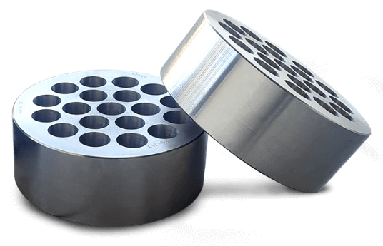
Bearing Plate
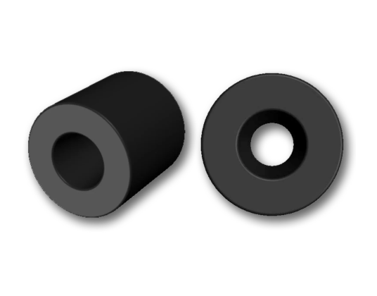
Barrel - Mono

Bearing Plate
Technical Specification
| Sr.No. | HTS Size (mm) | Anchor Head (code) | D Diameter (mm) | T Thickness (mm) | Conical Holes (Nos) |
|---|---|---|---|---|---|
| 1 | 12.70 | KTC 4KT13 (R) | 80 | 40 | 4 |
| 2 | KTC 7KT13 (R) | 100 | 40 | 7 | |
| 3 | KTC 12KT13 (R) | 130 | 50 | 12 | |
| 4 | KTC 19KT13 (R) | 160 | 60 | 19 | |
| 5 | KTC 27KT13 (R) | 200 | 75 | 27 | |
| 6 | 15.20 | KTC 4KT15 (R) | 120 | 45 | 4 |
| 7 | KTC 7KT15 (R) | 150 | 50 | 7 | |
| 8 | KTC 12KT15 (R) | 160 | 50 | 12 | |
| 9 | KTC 19KT15 (R) | 200 | 60 | 19 | |
| 10 | KTC 27KT15 (R) | 230 | 80 | 27 |
Barrel - Mono
Technical Specification
| Sr.No. | HTS Size | Barrel (code) | L Length (mm) | D Diameter (mm) | Conical Holes |
|---|---|---|---|---|---|
| 1 | 12.70 | KTB 13-50 | 50 | 50 | As per Gauge |
| 2 | KTB 13-55 | 55 | 55 | ||
| 3 | 15.20 | KTB 15-50 | 50 | 60 | |
| 4 | KTB 15-60 | 60 | 60 |
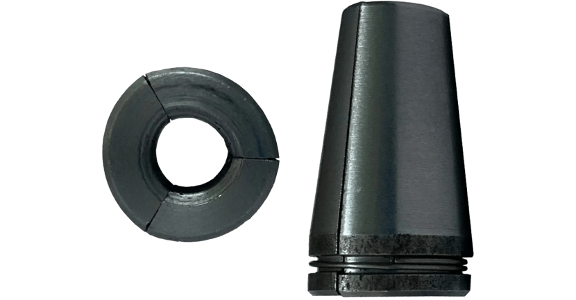
Wedges
Wedges consist of conical-shaped components that are divided into three equal parts and secured around the strand using specialized wire circlips. The concave portion of each slit features threading that functions like a jaw, ensuring secure locking after undergoing stress. To attain exceptional quality and strength, precise hardening and tempering treatments are meticulously applied.
Live Wedges
- Single Use Live Wedges
- Multi Use Live Wedges.
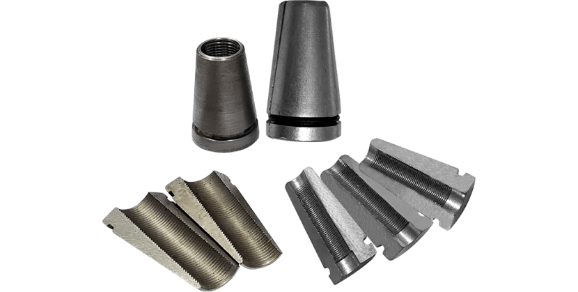
Master Wedges
Live Wedges
Technical Specification - Anchorages System
| Sr.No. | HTS Size | Anchor type | UTS (Tons) | 75% UTS | Duct Dia | Anchor Cone Size | Anchor Cone Length | Pocket (Recess) | Min.Edge Distance Anchorages | Spacing Between Anchorages | Pocket Depth | PCD of Anchor Fixing Holes | Anchor Head Dia | Anchor Head Thickness | Spiral Bar Details | ||||
|---|---|---|---|---|---|---|---|---|---|---|---|---|---|---|---|---|---|---|---|
| Spiral Dia | Spiral Length | Pitch Length | No. of Turns | Spiral Bar Dia | |||||||||||||||
| A | B | C | DxD | E | F | G | H | I | J | K | L | M | N | od | |||||
| 1 | HTS DIA 12.7 mm | 4K13 | 75 | 56 | 50 | 145 | 120 | 215 | 120 | 220 | 105 | 130 | 80 | 40 | 150 | 240 | 40 | 6 | 16 |
| 2 | 7K13 | 131 | 98 | 63 | 170 | 140 | 240 | 120 | 220 | 105 | 150 | 100 | 40 | 180 | 240 | 40 | 6 | 16 | |
| 3 | 12K13 | 225 | 169 | 92 | 190 | 140 | 270 | 148 | 260 | 120 | 165 | 130 | 50 | 200 | 480 | 60 | 8 | 16 | |
| 4 | 19K13 | 356 | 267 | 97 | 247 | 155 | 330 | 198 | 325 | 120 | 200 | 160 | 60 | 250 | 540 | 60 | 9 | 16 | |
| 5 | 27K13 | 506 | 380 | 120 | 305 | 230 | 380 | 295 | 485 | 120 | 275 | 200 | 75 | 300 | 600 | 60 | 10 | 20 | |
| 7 | HIS DIA 15.2 mm | 4K15 | 106 | 80 | 63 | 170 | 140 | 240 | 120 | 220 | 120 | 150 | 120 | 45 | 180 | 480 | 60 | 8 | 16 |
| 8 | 7K15 | 186 | 140 | 92 | 190 | 140 | 270 | 148 | 260 | 120 | 165 | 150 | 50 | 200 | 480 | 60 | 8 | 16 | |
| 9 | 12K15 | 319 | 239 | 97 | 247 | 155 | 330 | 200 | 300 | 120 | 200 | 160 | 50 | 250 | 540 | 60 | 9 | 16 | |
| 10 | 19K15 | 505 | 379 | 120 | 290 | 200 | 360 | 213 | 350 | 120 | 235 | 200 | 60 | 300 | 600 | 60 | 10 | 20 | |
| 11 | 27K15 | 718 | 539 | 160 | 350 | 350 | 430 | 340 | 575 | 130 | 285 | 230 | 80 | 360 | 720 | 60 | 12 | 20 | |
Master Wedges
Technical Specification - Anchorages System
| Sr.No. | HTS Size | Anchor type | UTS (Tons) | 75% UTS | Duct Dia | Anchor Cone Size | Anchor Cone Length | Pocket (Recess) | Min.Edge Distance Anchorages | Spacing Between Anchorages | Pocket Depth | PCD of Anchor Fixing Holes | Anchor Head Dia | Anchor Head Thickness | Spiral Bar Details | ||||
|---|---|---|---|---|---|---|---|---|---|---|---|---|---|---|---|---|---|---|---|
| Spiral Dia | Spiral Length | Pitch Length | No. of Turns | Spiral Bar Dia | |||||||||||||||
| A | B | C | DxD | E | F | G | H | I | J | K | L | M | N | od | |||||
| 1 | HTS DIA 12.7 mm | 4K13 | 75 | 56 | 50 | 145 | 120 | 215 | 120 | 220 | 105 | 130 | 80 | 40 | 150 | 240 | 40 | 6 | 16 |
| 2 | 7K13 | 131 | 98 | 63 | 170 | 140 | 240 | 120 | 220 | 105 | 150 | 100 | 40 | 180 | 240 | 40 | 6 | 16 | |
| 3 | 12K13 | 225 | 169 | 92 | 190 | 140 | 270 | 148 | 260 | 120 | 165 | 130 | 50 | 200 | 480 | 60 | 8 | 16 | |
| 4 | 19K13 | 356 | 267 | 97 | 247 | 155 | 330 | 198 | 325 | 120 | 200 | 160 | 60 | 250 | 540 | 60 | 9 | 16 | |
| 5 | 27K13 | 506 | 380 | 120 | 305 | 230 | 380 | 295 | 485 | 120 | 275 | 200 | 75 | 300 | 600 | 60 | 10 | 20 | |
| 7 | HIS DIA 15.2 mm | 4K15 | 106 | 80 | 63 | 170 | 140 | 240 | 120 | 220 | 120 | 150 | 120 | 45 | 180 | 480 | 60 | 8 | 16 |
| 8 | 7K15 | 186 | 140 | 92 | 190 | 140 | 270 | 148 | 260 | 120 | 165 | 150 | 50 | 200 | 480 | 60 | 8 | 16 | |
| 9 | 12K15 | 319 | 239 | 97 | 247 | 155 | 330 | 200 | 300 | 120 | 200 | 160 | 50 | 250 | 540 | 60 | 9 | 16 | |
| 10 | 19K15 | 505 | 379 | 120 | 290 | 200 | 360 | 213 | 350 | 120 | 235 | 200 | 60 | 300 | 600 | 60 | 10 | 20 | |
| 11 | 27K15 | 718 | 539 | 160 | 350 | 350 | 430 | 340 | 575 | 130 | 285 | 230 | 80 | 360 | 720 | 60 | 12 | 20 | |
Approved by
National Highway authority of India(NHAI)
Various Metro Corporations
Various State Road Development Authorities
Others....
Tested and passed by 3rd Party Test Laboratories
Indian Institute of Technology (IIT) – Chennai
AnuLab Industrial Testing & Analytical Laboratories, Agra
Our Clientele
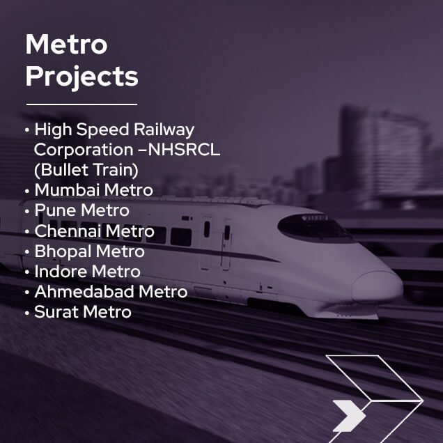
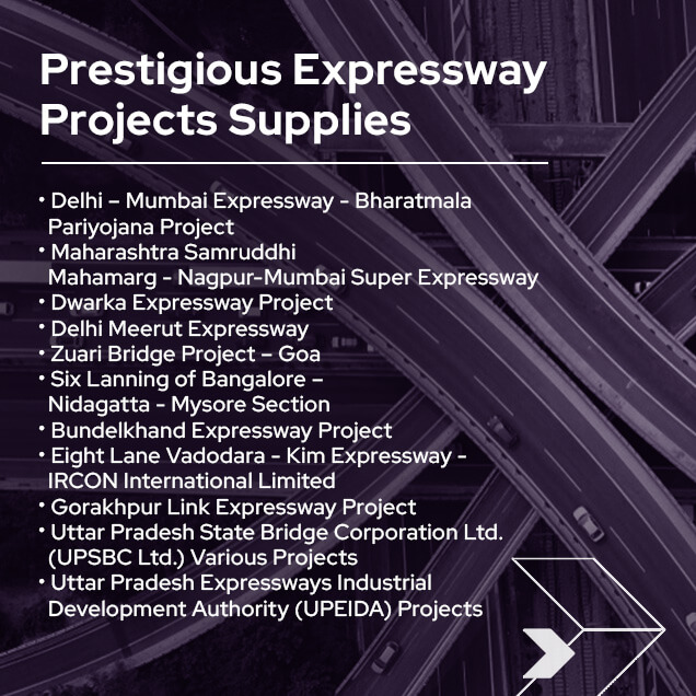
Major Projects

Our Product Range